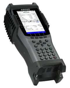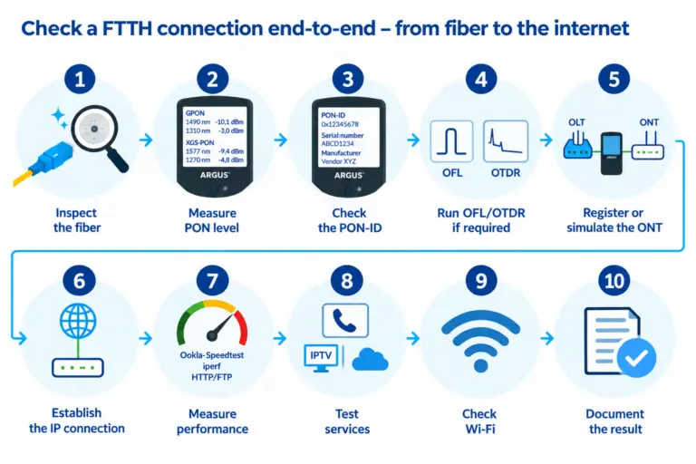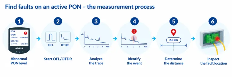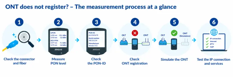
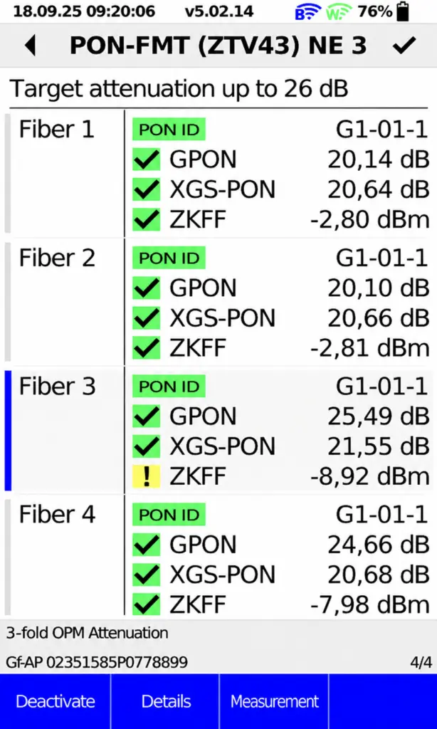
When accepting a GPON or XGS-PON connection, it is not enough to simply measure an optical level. What matters is whether the measured value matches the actual network topology and whether the technician is actually at the intended PON branch. The PON-FMT acceptance test according to ZTV 43 is an automated test and measurement procedure for checking continuity, cross-connections, and ensuring the quality of the Gf-AP all the way to the OLT. During this process, the PON-ID is used to identify the corresponding OLT port, and the insertion loss of the relevant wavelengths is determined simultaneously. The ARGUS guides the technician through the measurement like an assistant, automatically calculates the expected target insertion loss, and then evaluates the measurement result as OK or nOK. In addition, the PON-ID is determined to ensure that the measurement is performed on the correct PON branch. No login to the OLT is required. The key advantage over a simple level measurement: The technician does not merely receive a dBm value that he must interpret himself. Instead, the measurement answers the crucial questions: Does this specific GPON/XGS-PON connection meet the expected attenuation, and was the correct fiber measured?
What is a PON-FMT measurement according to ZTV43?
The abbreviation PON-FMT stands for “PON Fast Measurement Telekom.” The PON-FMT option is designed for measurements on GPON and XGS-PON connections in accordance with ZTV43. Instead of simply displaying the current optical level, the guided measurement procedure takes the existing network structure into account.
Based on the entered job and network data, ARGUS determines the target attenuation value relevant for acceptance testing and the number of fibers to be measured. The measured value is then automatically compared with the calculated target value and evaluated as OK or nOK.
The measurement can be saved and subsequently documented in a PDF acceptance report.
How does the PON-FMT measurement work?
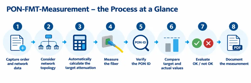
In simple terms, a PON-FMT measurement proceeds as follows:
Thanks to the guided process, the technician does not have to evaluate the measurement results solely based on a single level value. The evaluation takes into account the previously recorded network structure.
How is the target attenuation calculated?
First, the data relevant to the job is entered. After selecting the Gf-AP type, the number of residential units and the fiber length, among other details, can be specified. If there are multiple residential units, one or more couplers can also be taken into account.
Based on this information, ARGUS automatically determines the target attenuation relevant for acceptance testing and the number of fibers to be measured.
Why is the PON ID determined during the measurement?
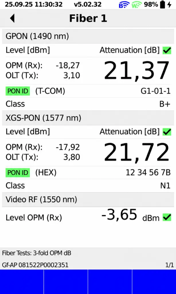
In addition to the optical level, the PON-ID is also determined during the PON-FMT measurement. This allows verification that the measurement is actually being performed on the intended PON branch. Registration with the OLT is not required for this.
Especially in more complex PON structures, the measurement thus not only provides the information “level present,” but also combines the level measurement with a verification of the PON branch and the calculated target attenuation.
What is the Level-ID Test (PIT) according to ZTV 43?
In addition to the PON FMT acceptance test, ZTV 43 describes the Level ID Test (PIT). In this test, the insertion loss for GPON at 1490 nm and—if present—for XGS-PON at 1577 nm is determined and verified at the Gf-AP. Additionally, the corresponding OLT port is identified via the PON ID.
The PIT is therefore primarily used to verify signal levels or attenuation and the correct PON assignment. This allows for the early detection of potential OLT port mix-ups or attenuation deviations.
Unlike the more comprehensive PON-FMT acceptance test, the PIT does not perform a target value calculation based on the entered network structure. The measured values for PON ID, level, and attenuation are evaluated for accuracy against the specified requirements.
Which wavelengths are measured during PON-FMT?
During the PON-FMT acceptance test, the relevant optical levels and attenuations can be measured simultaneously. These include 1490 nm for GPON, 1577 nm for XGS-PON, and—if available—1550 nm for ZKFF/TV.
Which ARGUS testers support PON-FMT?
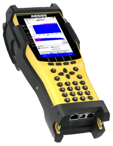
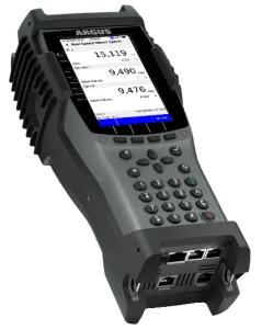
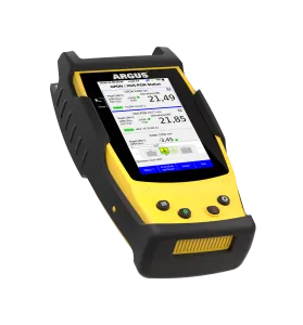
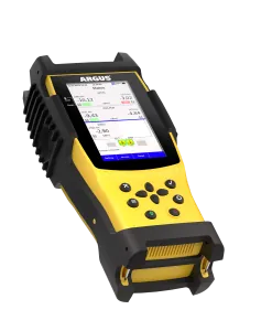
The ARGUS F200, F240, F300, 260, and 300 testers, when equipped with the appropriate OPM, support PON-FMT acceptance testing in accordance with ZTV 43 (April 2026 version). Depending on the OPM configuration, the F-series devices can measure the optical levels of GPON and XGS-PON, and—with the 5xOPM—additionally measure the 1550-nm level for ZKFF/TV.
How is the PON-FMT acceptance test documented?
Documentation is an integral part of the measurement process. Measurements can be temporarily saved and resumed at a later time.
The measurement results can be documented in a PDF acceptance report. Saved reports can be copied to a USB flash drive, transferred via FTP, or accessed via WLAN using the web interface, WebDAV, or the ARGUS Mobile App.
This ensures that the measurement values, the automatic evaluation, and the associated order data remain traceable even after the acceptance measurement is complete.
This results in a reproducible acceptance process with traceably documented measurement results.
PON-FMT According to ZTV43 at a Glance
| Function | PON-FMT |
|---|---|
| Measurement Procedure | Guided |
| Setpoint Damping | Automatic calculation |
| Evaluation | Automatic OK/nOK |
| PON ID | Being determined |
| Registration at the OLT | No |
| GPON | 1490 nm |
| XGS-PON | 1577 nm |
| ZKFF/TV | 1550 nm, if available |
| GPON upstream | 1310 nm, depending on the equipment |
| XGS-PON upstream | 1270 nm, depending on the equipment |
| Documentation | including PDF acceptance report |
Technical Data for Level Measurement
| Specifications | Value |
|---|---|
| Accuracy | ±0.5 dB at -20 dBm |
| 3xOPM Measurement Range | -40 to +6 dBm |
| 5xOPM measurement range | 5xOPM measurement range |
| 1550-nm range | -50 to +13 dBm |
| Documentation | including PDF, USB, FTP, WLAN/WebDAV/App |
Further information on PON-FMT and the ARGUS testers
For further technical details, please refer to the PON-FMT flyer and the respective product pages for the ARGUS testers.