Optical Loss Test Set in Fibre-Optic Network Deployment
Fachartikel NET 04/2025
What matters is the result
A wide range of measurement methods are used in fibre-optic roll-outs – including the so-called attenuation test set, also known as an Optical Loss Test Set (OLTS). But can attenuation actually be measured? A brief overview.
“What could possibly go wrong with a fibre-optic roll-out? If the cables are laid properly and
light is switched on along the cable, then it’ll work.” You hear statements like this time and again. But why are there so many different measurement methods in the field of fibre-optic technology? This article aims to examine one of the simplest yet most efficient methods: the Optical Loss Test Set, also known as the ‘optical attenuation test’, often mistakenly referred to as an attenuation measurement.
But let’s start at the beginning: Anyone who has changed a light bulb at home knows – even as a child – what to do next: flick the light switch and check whether the bulb is lit. Why should one deviate from this simple and tried-and-tested method when installing fibre-optic cables?
So, if you suspect no fault but rather that the fibres have been laid correctly, you shine a light onto the start of the fibre and see how much of it still reaches the other end after 2, 4 or 8 km of cable. That is exactly what an Optical Loss Test Set does.
It hardly matters which technology (point-to-point; PON, etc.) is subsequently rolled out on the line. If the signal arrives reliably and a sufficient margin is allowed for, depending on the sensitivity of the receivers, it can be assumed that the installation meets at least the basic requirements. This provides valuable evidence – particularly when handing over the completed line section to the client.
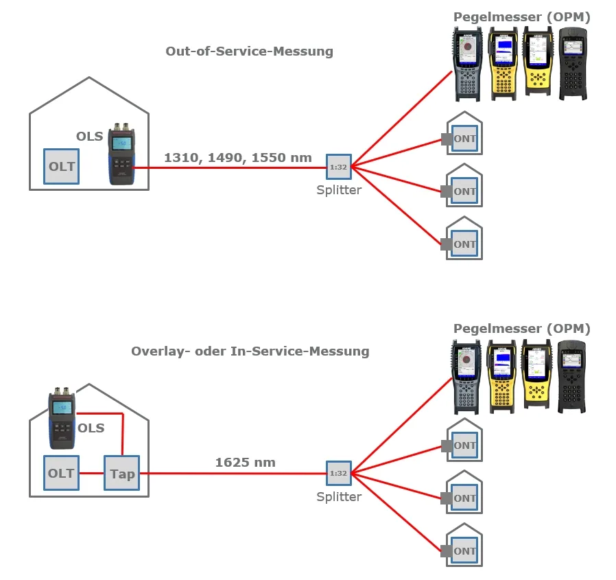
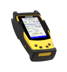
Connection of the OLS and OPM during an out-of-service or in-service measurement (overlay measurement).
Not an attenuation measurement
In what is known as an attenuation measurement, the level at the end of the line is actually measured – it is therefore an optical level measurement and not a measurement of attenuation. The difference from ‘normal’ level measurement on lines that are already active and carrying light is that, in an ‘optical attenuation test’, there is no active equipment – i.e. no light source – on the line, and this must be provided. An optical loss test set therefore always consists of two parts: a light source, also known as an optical light source (OLS), and a light meter, also known as an optical power meter (OPM). The light source injects a defined optical level at a specified wavelength into the optical fibre cable with as little insertion loss as possible.
The difference between the already known and precisely defined transmission level and the exact optical level measurement at the other end of the line represents the attenuation of the link and is therefore the result of a calculation: attenuation is thus not measured, but calculated. For this reason, the English term ‘OLTS’ is more appropriate than the German term ‘Dämpfungsmessset’ – even though the latter is frequently used in DIN or VDE standards (for example, DIN EN 61280 or DIN EN 50346).
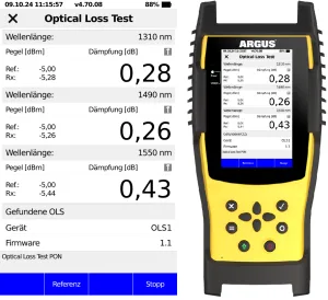
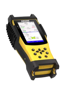
Display of results from an automated Optical Loss Test as an out-of-service measurement across three wavelengths.
Optical Light Source
A typical insertion level suitable for most routes and technologies is, for example, -5 dBm, known as the transmit power. Injecting higher levels – comparable, for example, to those of an OLT (Optical Line Terminal) – would carry the risk of non-linearities and distort the level metre’s readings due to saturation. Furthermore, the use of lower levels is safer for the user: A level of -5 dBm corresponds to a power of approximately 0.3 mW and is therefore within the eye-safe range. The high levels of an OLT are designed to transmit usable signals over the greatest possible distances, whilst the transmission level of an OLS is intended to achieve precise measurements.
It is particularly important that the light source transmits at a constant transmission level and with a stable wavelength. Deviations of up to ±0.5 dB in the transmission level and a further maximum of ±0.1 dB over time, as well as ±10 nm in wavelength, are still acceptable. Ideally, OLSs and OPMs are calibrated by the manufacturer and supplied with a certificate of calibration. It is strongly recommended that the calibration be repeated every two years.
To be able to ‘simulate’ the vast majority of single-mode fibre technologies, two wavelengths are often sufficient (minimum requirement): Firstly, the wavelength of 1550 nm; this lies within the third optical window of fibre-optic transmission and exhibits the lowest attenuation per kilometre of line length. Furthermore, the video overlay signal in GPON
or XGS-PON
networks is often superimposed here in order to feed a broadcast TV signal with the widest possible reach as a unidirectional downstream signal.
Secondly, the wavelength of 1310 nm is recommended; this lies within the second optical window of fibre-optic transmission and is used for upstream transmission in widely deployed GPON
networks, but also in active point-to-point technologies, namely fibre-optic-based Ethernet
connections and so-called AONs (Active Optical Networks). Furthermore, 1310 nm exhibits the lowest chromatic dispersion. This means that non-ideal, non-monochromatic lasers emit within a specific spectral range, and different components of the light – for example, the short-wavelength and long-wavelength components – arrive at different times, thereby distorting or broadening the signal. This can cause problems, particularly over long distances and/or at high transmission rates.
If you want to be on the safe side, you should also schedule a measurement at 1490 nm – this is the most important downstream wavelength for the widely used GPON
.
In addition, a wavelength such as 1625 nm can also be considered for so-called in-service measurements. Even if the links have already been activated and data is actively being transmitted between the OLT and the ONT (Optical Network Terminal), a so-called overlay measurement is still possible. The OLS is then, for example, looped in on the OLT side and provides a good approximation without having to take the entire branch offline. It is important to note that the ONTs must be able to filter out the 1625 nm signal.
If a multi-wavelength OLS is used, for example at 1310, 1490 and 1550 nm, to check the exact link loss of a fibre for use in a GPON
network, it is also extremely helpful if the OLS immediately informs the OPM of the transmit power level at which it is transmitting on each wavelength. This allows the level metre on the opposite side to determine the exact optical level at each wavelength in turn and to display all values at once in a clear overview within seconds. Such automated, protocol-based transmission of the wavelength and transmit power (Tx power) is indispensable if one does not wish to make every setting manually. Particularly when commissioning hundreds of newly laid fibres, this Auto Mode not only saves a considerable amount of time but also significantly reduces the likelihood of errors. Such a feature is essential and should under no circumstances be overlooked when selecting equipment.
An in-service measurement at a wavelength such as 1625 nm should definitely be provided separately, for example via an SC/APC socket. This prevents all users in an active network from being inadvertently disrupted by transmission on live wavelengths such as 1310, 1490 or 1550.
An often underestimated but important function is logging. Simple solutions display the measured values on a 7-segment display or – somewhat more modern – on an LCD screen. As the measured values cannot be saved or transferred directly to a cloud, a PC, a smartphone or a database for documentation and archiving, the only option is manual documentation – a time-consuming and error-prone process. Values are recorded incorrectly, misallocated or forgotten. File formats such as HTML or CSV, which can be quickly retrieved from the measuring device using a smartphone, as well as transmission via QR code, are now standard practice and indispensable.
Documented acceptance measurements not only demonstrate the quality of one’s own work, but can also – if not already required – be invoiced to the client as an additional service. Furthermore, in the event of a dispute, they constitute a quality assessment in their own right, which can be decisive.
However important technical specifications and the highest measurement accuracy may be – the following always applies to all work: the absolute cleanliness and integrity of the connectors is the top priority.
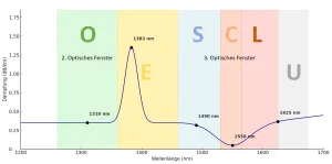
Realistic attenuation curve of a single-mode fibre (PON) with bands, as well as the second and third optical windows.
Challenges and solutions
There is a wide variety of solutions available on the market, and each area of application has its own specific procurement requirements. Should you buy a set consisting of two individual devices in a case, or would a single device that covers everything be preferable? Even if you know exactly which technical parameters to look out for when making your selection, flexibility is a major advantage here. Areas of use and applications are constantly changing – in particular, the need to carry out and document acceptance tests for new installations is subject to fluctuations. These are often caused by changing clients or by evolving standards and guidelines.
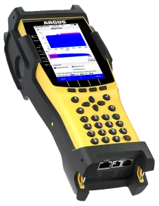
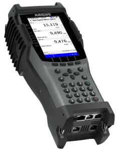
intec Gesellschaft für Informationstechnik mbH develops high-precision measurement solutions for a wide range of applications. For example, existing measuring devices – some of which date back to the DSL era – that are equipped with an SFP port can be upgraded to an OLTS by using a highly compact SFP-OPM. Even OTDR devices that have already been purchased, or full-fledged PON speed metres with genuine ONT simulation and IP speed tests up to 10 Gbit/s, can be upgraded in this way quickly and cost-effectively to a fully-fledged OLTS. There is not even any need to send the device itself in for modification – a real practical advantage for intensive field use. Should the slot used in the device become worn due to frequent plugging and unplugging, it can be easily replaced by swapping the module in SFP-based systems.
The solutions from the Lüdenscheid-based company, all of which are developed and manufactured in Germany, cover the entire spectrum of fibre-optic measurement technology, ranging from a simple retrofit solution using SFP, through the compact and cost-effective power metre (3xOPM) for filtered (selective) measurements at the critical live wavelengths of 1490 nm (GPON) and 1577 nm (XGS-PON), right through to broadband OPM measurements for OLTS operation. Furthermore, they offer multifunctional devices that can combine an OTDR, a 5xOPM with through-mode, an inspection tool for checking fibre end-faces, as well as comprehensive connection tests for GPON, XGS-PON, Ethernet and WLAN networks, and OLTS functionality, all within a single system.
Conclusion and Outlook
The advantages of the OLTS are therefore immediately apparent: it offers high measurement accuracy when determining the actual attenuation of a link – particularly during acceptance testing following installation and maintenance. Added to this are compliance with numerous national (see above) and international standards (for example, ISO/IEC 14763-3, TIA-568), quick and easy set-up, and extremely straightforward operation and analysis. The disadvantages of an OLTS are that neither precise fault localisation nor reflection measurement is possible – an OTDR is still required for this. Furthermore, measurement with an OLTS requires access to both ends of the fibre.
An OTDR is ideal for fault diagnosis, but not for precise attenuation measurements. An OPM only measures the incoming power from active equipment (for example, the OLT’s transmit level) – to determine the line attenuation precisely, an additional constant light source and a reference measurement are required. The Optical Loss Test Set simply measures more accurately – what really matters is what actually arrives.