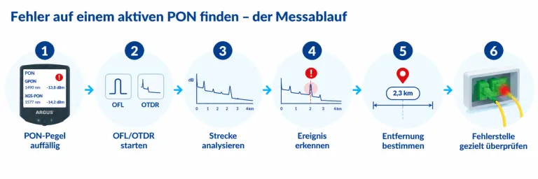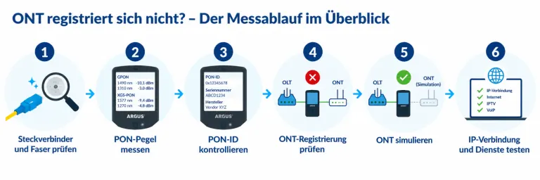
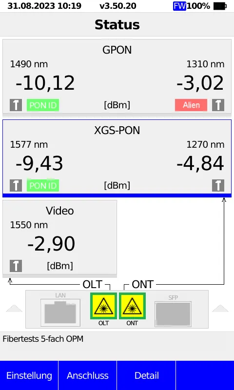
GPON and XGS-PON can be transmitted in parallel over the same optical fibre, as both technologies use different wavelengths. For the technician, this means that several optical signals may be present simultaneously at a single connection. To assess these correctly, the individual wavelengths must be measured separately. A selective or filtered PON power metre is used for this purpose. It can distinguish between the relevant GPON and XGS-PON wavelengths and measure their optical levels separately.
What wavelengths do GPON and XGS-PON use?
GPON and XGS-PON use different wavelengths for downstream and upstream:
| Technology | Downstream | Upstream |
|---|---|---|
| GPON | 1490 nm | 1310 nm |
| XGS-PON | 1577 nm | 1270 nm |
Particularly when gradually upgrading existing GPON networks to XGS-PON, this can result in mixed operation, whereby both technologies are transmitted simultaneously over the same fibre.
Why is a simple power metre not sufficient?
A simple broadband power metre measures the optical power, but cannot specifically distinguish between the simultaneously present PON wavelengths.
A plausible total reading therefore does not automatically mean that both the GPON and XGS-PON levels are within the specified range.
A selective or filtered PON power metre, on the other hand, separates the relevant wavelengths and enables them to be measured and evaluated individually. This makes it possible, for example, to distinguish which level belongs to the GPON signal and which to the XGS-PON signal.
What is ‘Through Mode’ in a PON measurement?
The measurement becomes even more meaningful in Through Mode. In this mode, the measuring instrument is connected between the PON and the ONT. The connection remains intact whilst the optical signals between the OLT and the ONT are measured.
This allows downstream and upstream signals to be analysed whilst the PON system is in operation.
This is particularly relevant for the upstream: whilst the OLT transmits continuously in the downstream, the individual ONTs transmit in the upstream only within their allocated time slots. The PON power meter must therefore also be able to detect these burst-like upstream signals.
How does the simultaneous measurement of GPON and XGS-PON work?
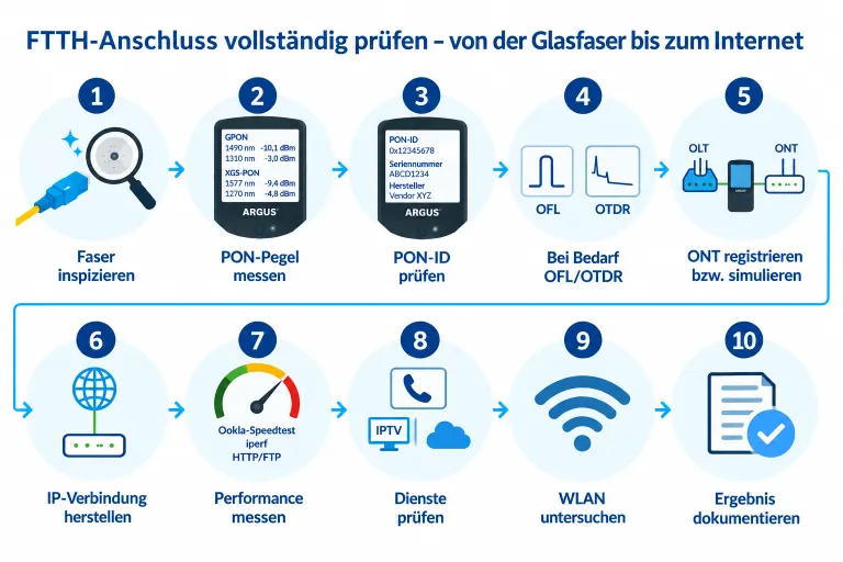
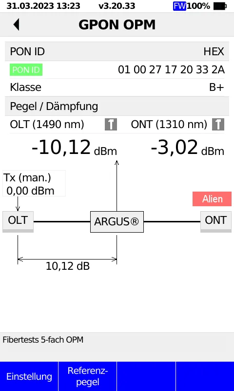
In simple terms, the measurement procedure is as follows:
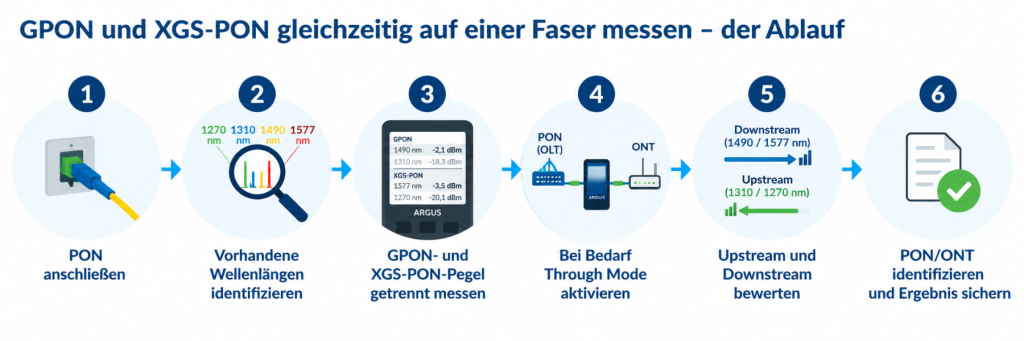
This means that the technician not only receives information that an optical signal is present, but can also assess the various PON signals separately.
Which ARGUS testers can measure GPON and XGS-PON?
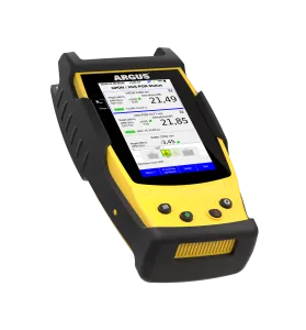
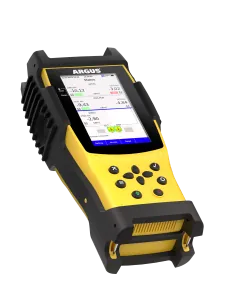
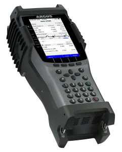
For the parallel measurement of GPON and XGS-PON, the ARGUS F200, ARGUS F240 and ARGUS F300 – depending on their respective configurations – offer selective PON measurement functions.
The selective power metre can be connected to an existing PON connection in Through Mode and determine the optical levels of the various downstream and upstream wavelengths. Furthermore, depending on the configuration, additional PON information such as the PON ID can be determined, and alien ONTs on the line can be detected.